I’m doing a complete rewire of my 1976 21’ Fiberform (new to me). 165 Merc I/O. I’ve got it all planned out but have a couple things to clarity before I purchase the cables and lugs online.
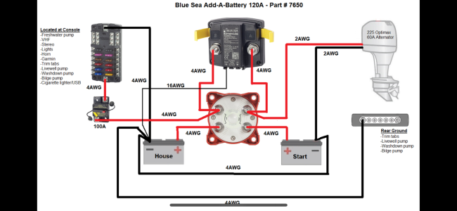
I’m doing a Blue Sea Add A Battery with 2 fuse blocks to distribute the power to the accessories (one at the helm, one at the stern). Their documentation shows a circuit breaker or fuse on the wire between the battery switch and the fuse blocks, but I can’t find how to rate the amperage of the breaker or fuse. Any tips here? Both fuse blocks will be near their 100A capacity.
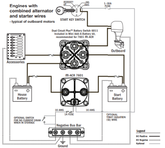
I’m connecting the larger negative cables on a negative bus at the stern. I will run a negative cables from there to and from the engine. Do I also need to run a separate cable to ground the negative bus on the engine block?
Thanks
I’m doing a Blue Sea Add A Battery with 2 fuse blocks to distribute the power to the accessories (one at the helm, one at the stern). Their documentation shows a circuit breaker or fuse on the wire between the battery switch and the fuse blocks, but I can’t find how to rate the amperage of the breaker or fuse. Any tips here? Both fuse blocks will be near their 100A capacity.
I’m connecting the larger negative cables on a negative bus at the stern. I will run a negative cables from there to and from the engine. Do I also need to run a separate cable to ground the negative bus on the engine block?
Thanks