Rewiring questions

MR fisher

Member
I’m doing a complete rewire of my 1976 21’ Fiberform (new to me). 165 Merc I/O. I’ve got it all planned out but have a couple things to clarity before I purchase the cables and lugs online.

I’m doing a Blue Sea Add A Battery with 2 fuse blocks to distribute the power to the accessories (one at the helm, one at the stern). Their documentation shows a circuit breaker or fuse on the wire between the battery switch and the fuse blocks, but I can’t find how to rate the amperage of the breaker or fuse. Any tips here? Both fuse blocks will be near their 100A capacity.

I’m connecting the larger negative cables on a negative bus at the stern. I will run a negative cables from there to and from the engine. Do I also need to run a separate cable to ground the negative bus on the engine block?

Thanks
Blue Sea's website has a lot of articles on wiring your boat. The chart in this link http://assets.bluesea.com/files/resources/newsletter/images/DC_wire_selection_chartlg.jpg
is good for selecting your wire size for your load.
Then you can select the breaker or fuse to protect the wire and fuse block. For your almost fully loaded 100 amp fuse blocks you would probably use 100 amp fuses at the battery switch and 4 gauge to 1 gauge wire depending on the distance from the fuse block to the battery switch. Bigger the wire the less voltage drop you will have but the more it will cost.
 
I’m doing a complete rewire of my 1976 21’ Fiberform (new to me). 165 Merc I/O. I’ve got it all planned out but have a couple things to clarity before I purchase the cables and lugs online.

I’m doing a Blue Sea Add A Battery with 2 fuse blocks to distribute the power to the accessories (one at the helm, one at the stern). Their documentation shows a circuit breaker or fuse on the wire between the battery switch and the fuse blocks, but I can’t find how to rate the amperage of the breaker or fuse. Any tips here? Both fuse blocks will be near their 100A capacity.

I’m connecting the larger negative cables on a negative bus at the stern. I will run a negative cables from there to and from the engine. Do I also need to run a separate cable to ground the negative bus on the engine block?

Thanks
The breaker should be set to the max current (amperage) rating of the wire you are running from the battery to fuse block. Rating is based on length and gauge. If your engine block’s ground is connected to the battery negative, you shouldn’t need to add another ground to a bus bar that’s also connected to the battery negative. Can easily test to make sure you have electric continuity between all your ground points in your system if you have any doubts
 
Thanks guys. The Blue Sea chart and Circuit Wizard are great resources. I wasn't sure though about sizing the breaker or fuse though. One of the runs is going to be about 16' (2AWG) but the other is minimal - the block will be within a foot of battery switch.

With respect to the bus bar, I was planning negative runs from both batteries to the bus bar, as well as both fuse blocks, the main engine starter, and the ACR. Does that sound about right?
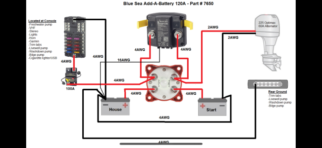
I dug this schematic off the internet. Does it seem relevant to your application?
 

Attachments

  • IMG_7964.png
    IMG_7964.png
    519.1 KB · Views: 32
I dug this schematic off the internet. Does it seem relevant to your application?
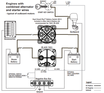
I think so. Pretty similar to my setup. One difference is I have a 42A output on the alternator so I went with the Mini Add A Battery. Here is their schematic. Shows a negative going to the main engine and also to a ground. I'm not certain how my situation differs being on an I/O.
 

Attachments

  • mini aab.png
    mini aab.png
    120.7 KB · Views: 23
I think so. Pretty similar to my setup. One difference is I have a 42A output on the alternator so I went with the Mini Add A Battery. Here is their schematic. Shows a negative going to the main engine and also to a ground. I'm not certain how my situation differs being on an I/O.
Yeah, I see that. I have never bonded a DC system to earth, only on AC systems. I think it depends on your system configuration and boat. I definitely would not on an aluminum boat due to electrolytic corrosion concerns. Seems to be a contentious topic, but this is a thread discussing it:


I think the main concern is having a ground point if your AC system finds a way to connect to the DC system, you have a path to ground so you don’t get electrocuted
 
Last edited:
This makes sense. Thanks Alex. Except for charging batteries when necessary I don't see AC ever being around my system, so it's probably not a concern. I will discuss with an electrician friend though also.
 
Back
Top